
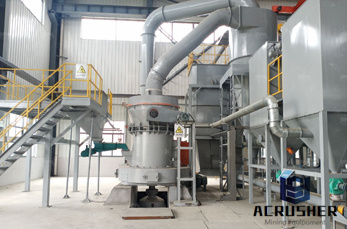
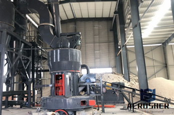
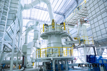
typical process flow diagram for coal manufacturer Grasping strong production capability, advanced research strength and excellent service, Shanghai typical process flow diagram for coal supplier create the value and bring values to all of customers.
 WhatsApp)
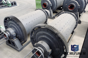
The flow scheme of Figure 2 represents a typical process arrangement of a nearterm commercial IGCC design without CO 2 capture. CO 2 capture and sequestration (CCS) significantly impacts the overall IGCC efficiency, and the effects are addressed in .
A typical Process Flow Diagram (or PFD) explains the process for pygas processing or pygas hydrotreating. Pyrolosis gasoline or pygas (C5+ cut) is a liquid byproduct derived from steam cracking of various hydrocarbon feedstocks in olefin plants. A typical Process Flow Diagram (or PFD) explains the process for pygas processing or pygas ...
Typical Process Configurations The DCL process involves adding hydrogen (hydrogenation) to the coal, breaking down its organic structure into soluble products. The reaction is carried out at elevated temperature and pressure (, 750 to 850°F and 1,000 to 2,500 psia) in the presence of a solvent.
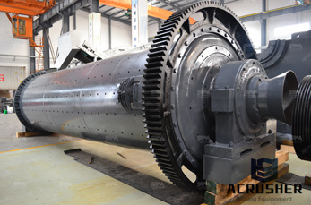
Figure 44 presents the process flow diagram for a typical coal ... Coal slurry pipelines require coalliquid slurry preparation at the upstream ... the pipeline as a contingency for downtime of the coalusing facility. Pipelines. Get Price. Coal Preparation Plant Advancements Mining USA.
general process diagram of a coal mine . process diagram of a typical coal mine plant General Mining Engineering Find extract and prepare coal metals, Flow Process Diagram Coal Mining, process diagram of a typical coal mine plant diagram of a coal mineGrinding Mill China general process flow diagram of a coal mine Grinding is theprocess diagram of a typical coal mine plantbowl
At present % or MW (Data Source CEA, as on 31/03/2011) of total electricity production in India is from Coal Based Thermal Power Station. A coal based thermal power plant converts the chemical energy of the coal into electrical energy.
The condensate water flow rate in a 500 MW coalfired power plant is about 23,000 litres per minute. ... Diagram of the overall conventional coalfired power plant. Simplified coalfired power plant ... estimated that the amount of coal burned each year in a typical 1000 MW coalfired power plant contained about tonnes of uranium and about ...
Figure illustrates the major process equipment in a schematic diagram of a byproduct coke oven battery. Flow diagrams are provided in Figures and 3 to give an overview of the process from coal preparation to byproduct recovery. These operations will be discussed in greater detail for the
typical process flow diagram for coal . a typical flow sheet of a coal processing process flow diagram for a typical coal cleaning plant is Fine coal processing and coarse coal processing use Live Chat Process Of Coal Mining Diagrammayukhportfolio. Get Price water balance diagram for thermal power plant BINQ
A process flow diagram for a typical coal cleaning plant is presented in Figure In the initial preparation phase of coal cleaning, the raw coal is unloaded, stored, conveyed, crushed, and classified by screening into coarse and fine coal .
As shown in the process flow diagram, the coal is first slurried with water and fed to the first stage of the gasifier. Oxygen with a purity of 95% is provided from the Air Separation Unit (ASU) and the coal is partially combusted to maintain a temperature of 1370 °C.
A process flow diagram for a typical coal cleaning plant is presented in Figure In the initial preparation phase of coal cleaning, the raw coal is unloaded, stored, conveyed, crushed, and classified by screening into coarse and fine coal .
Thermalbased power plants can produce electricity from coal or other fuel sources. The coalfired process requires three different steps to turn energy released from burning coal to generating electricity for consumption. Coal fired power plants, while producing power, require a lot of water and produce a lot of pollutants like ash and CO2.
Coal Preparation Plant Advancements R. Q. Honaker University of Kentucky ... Typical Process Flow Sheet For Steam Coal Production Sieve Bends/ Clean Coal Cyclones Dense Medium Vessel DR Screens Clean ... coal. Required volumetric flow rate is around 15 gpm/start and feed solids content
CoalToLiquids (CTL) FischerTropsch Processing (FT) ... COAL FOR THE FT PROCESS Carbon forms more than 50% by weight more than 70% by volume of coal (this includes inherent moisture). ... Indiana Center for Coal Technology Research 5 CCTR TYPICAL PERCENTAGES OF CONTENT
This chapter covers different types of chemical process diagrams, how these diagrams represent different scales of process views, one consistent method for drawing process flow diagrams, the information to be included in a process flow diagram, and the purpose of operator training simulators and recent advances in 3D representation of different chemical processes.
The PFD example "Process flow diagram Typical oil refinery" was created using the ConceptDraw PRO diagramming and vector drawing software extended with the Chemical and Process Engineering solution from the Chemical and Process Engineering area of ConceptDraw Solution Park.
Mar 19, 2018· Coal is fuel here because we are going to draw the flow diagram of a coal thermal power generating plants. Coal creates required heat energy by combustion in the furnace. Air is supplied to the furnace to accelerate combustion rate of the coal and to continue the flow of .
Also called: process flowchart, process flow diagram. Variations: macro flowchart, topdown flowchart, detailed flowchart (also called process map, micro map, service map, or symbolic flowchart), deployment flowchart (also called downacross or crossfunctional flowchart), severalleveled flowchart. A flowchart is a picture of the separate ...
Coal Beneficiation Process Diagram. Coal processing has two forms, here descripe flow chart of coal processing plant: Industrial process is the coal after the coal crusher, with the belt conveyor to quantitative feeder, to pressure the ball machine feeding by quantitative feeder uniform, sometimes need to improve the coal briquette strength, therefore, quantitative feeder and intermediate ...
Flow Chart Symbols. You''ll notice that the flowchart has different shapes. In this case, there are two shapes: those with rounded ends represent the start and end points of the process and rectangles are used to show the interim steps.
Refinery Process Modeling, A Practical Guide to Steady State Modeling of Petroleum Processes, 1sted. Gerald Kaes, Athens Company, 02004 Updated: July 12, 2018
processing, and final preparation. A process flow diagram for a typical coal cleaning plant is presented in Figure In the initial preparation phase of coal cleaning, the raw coal is unloaded, stored, conveyed, crushed, and classified by screening into coarse and fine coal .
Coal preparation flow chartoal wikipediaa coal preparation plant is prep plant typical coal chart that washes coal of soil crushes it into graded coal needs to be stored stages of the preparation process and the cpp facilities.
WhatsApp)