
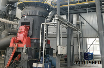
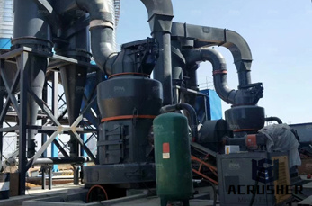
schematic figure of coal mill in a cement plant manufacturer Grasping strong production capability, advanced research strength and excellent service, Shanghai schematic figure of coal mill in a cement plant supplier create the value and bring values to all of customers.
 WhatsApp)
The plant layout is shown in Figure 1 and the outline process flow is shown in Figure 2. The heart of the process involves the electrolytic reduction of alumina (aluminum oxide) in a series of large cells (a Pot) – the Potlines. A schematic diagram of a cell is shown in Figure 3. In order to operate the cells (some 1080 in this case) a ...
Figure illustrates the major process equipment in a schematic diagram of a byproduct coke oven battery. Flow diagrams are provided in Figures and 3 to give an overview of the process from coal preparation to byproduct recovery. These operations will be discussed in greater detail for the
as a supplemental fuel to coal. Only one California plant utilizes gas as a primary kiln fuel. This is a relatively small plant that produces white cement. The remainder of the natural gas usage is associated with boiler and machine drive end uses. Figure 21 Cement Industry End Use Electricity Consumption Process Machine Drive 81% Process ...
Process control optimization of rotary kiln line, raw mill and coal mill at the Adana cement plant in Turkey 20% decrease in standard deviation, 10% longer refractory life, % energy saving, % production increase. System 800xA Electrical Control System for EPCC cement production line
Case Study of the California Cement Industry Fred Coito and Frank Powell, KEMA ... Labor is relatively small at a cement plant. Figure 1 shows historical consumption of energy by California cement plants. While coal is the primary ... A schematic of the cement production process is shown in Figure 3. The most common
Plants that burn waste fuels enjoy a negative fuel cost (they are paid by industries needing to dispose of materials that have energy content and can be safely disposed of in the cement kiln thanks to its high temperatures and longer retention times). As a result, the inefficiency of the wet process is an advantage—to the manufacturer.
Energy Efficiency Improvement and Cost Saving Opportunities for Cement Making An ENERGY STAR® Guide for Energy and Plant Managers August 2013 ENERGY STAR is a Environmental Protection Agency Program helping organizations and individuals fight climate change through superior energy efficiency. Document Number 430R13009
Crushing Plant Design and Layout Considerations Ken Boyd, Manager, Material Handling, AMEC Mining Metals, Vancouver, BC ABSTRACT In mining operations, the layout of crushing plants and ancillary equipment and structures is a crucial factor in meeting production requirements while keeping capital and operational costs to a minimum.
Jan 16, 2016· I''ve added some colour to the diagram to help clarify things and to give some indication of how the plant operates. It takes a great deal of energy to make paper, and the International Paper plant at North Tonawanda had its own powerhouse fueled by coal. During peak production times, the plant consumed as much as 150 tons of coal per day.
ROPOSED CEMENT PLANT SALIENT FEATURES OF THE CEMENT PLANT. Fig – shows the process flow diagram of the coal handling in the proposed cement plant. Six Stage Precalciner String The hot gases from the kiln will .
A plant or a piece test. Whether you are looking for an entire cement plant or a single piece of equipment, we are the premium supplier. For new plants, we cover everything from evaluating initial quarry samples through to ongoing operation and maintenance services.
A simplified diagram of the pulverised coal plant is presented in Fig. The illustration shows a simple schematic diagram for a typical pulverised coal combustion system. In this type of system, the coal is prepared by grinding to a very fine consistency for combustion. Typically, 70% of the coal is ground to pass through a 90 μm mesh screen.
Impact Mills Grinding Action is carried out by aseries of hinged or fixed hammers revolving in an Improving Coal Pulverizer Performance and Reliability Coal Conveyer Coal Crusher Raw Coal Bunker To Boiler Furnace Raw Coal Feeder Exhauster Hot Air Motor Coal Pulverizer Figure 1: Simplified diagram detailing a directfired coal burning system.
K. COAL FEED Figure 1. Schematic of the cement plant sampling points. process. A schematic depicting the process with designated sampling points is shown in Figure 1. To check the extent to which the blasting powder residue may contribute NH4+ to the process, grab samples were acquired at the limestone blasting area. Four samples were taken: two
Cement manufacturing: components of a cement plant. This page and the linked pages below summarize the cement manufacturing process from the perspective of the individual components of a cement plant the kiln, the cement mill etc.. For information on materials, including reactions in the kiln, see the '' Clinker '' pages.

Aug 30, 2012· This saves the extra fuel cost and makes cement somehow economical. Raw materials are extracted from the quarry and by means of conveyor belt material is transported to the cement plant. There are also various other raw materials used for cement manufacturing. For example shale, fly ash, mill scale and bauxite.
What is carbon dioxide capture and sequestration? Carbon dioxide (CO 2) capture and sequestration (CCS) is a set of technologies that can greatly reduce CO 2 emissions from new and existing coal and gasfired power plants and large industrial sources. CCS is a threestep process that includes: Capture of CO 2 from power plants or industrial processes ...
Feb 16, 2016· A stacker reclaimer for Limestone storage is shown in the video in a cement plant. Stackers and reclaimers are used in stockyards to stack minerals, ore, .
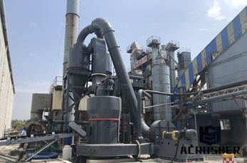
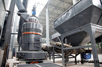
schematic figure of coal mill in a cement plant schematic figure of coal mill in a cement plantcement grinding optimisation However, in the cement industry, the grinding process is more of an. the schematic diagram of ground coal mining mechanical . Mining Equipments mobile asphalt plants for sale concrete sand supplier from malaysia in ...
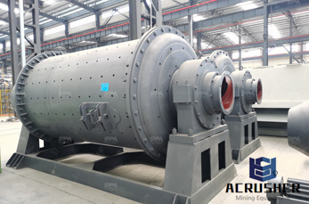
Figure 1 presents a diagram of the cement manufacturing process using a rotary kiln and cyclone preheater configuration. The schematic for a rotary kiln and precalciner configuration is very similar to that shown in Figure 1, with a calciner vessel located between the rotary kiln and cyclone preheater.
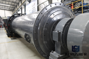
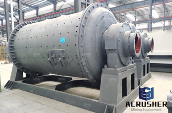
Nov 12, 2014· 3D Animation Demo working site of Ball Mill Henan Bailing. ... Ltd. ball mill is widely used in powdermaking production line including cement, silicate, newtype building material ...
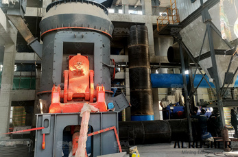
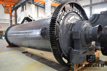
A cement mill (or finish mill in North American usage) is the equipment used to grind the hard, nodular clinker from the cement kiln into the fine grey powder that is cement is currently ground in ball mills and also vertical roller mills which are more effective than ball mills.
Section Formula for target setting for Coal based Thermal Power Plant 5 (a) Design Net Heat Rate 5 ... ExCoal/Lignite/Oil/Gas based Thermal Power Plant Energy balance diagram 156 Figure 10: ExCCGT Energy balance diagram 157 ... Ex GtG boundary and metering details for Agro based Pulp and Paper Mill 198 Figure 22: Ex GtG boundary for ...
Greater Detail: Cement Plant Operations Handbook Crewmen''s Guide, Finish Mill Systems Cement mill A 10 MW cement mill, output 270 tonnes per hour A cement mill (or finish mill in North American usage[1]) is the equipment used to grind the hard, nodular clinker from the cement kiln into the fine grey powder that is cement..
WhatsApp)